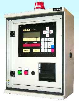
MANUAL CONTROL
(always provided) |
- Start/Stop by means of proper buttons
- Output voltage (current) adjustment by means of potentiometer knob(s) on the control panel
- Anodizing time adjustable by means of timer on the control panel.
|
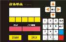
AUTOMATIC CONTROL
by means of
APC
(provided on request) |
- Start/Stop by means of proper buttons
- Current density (A/dm2) and thickness (micron) presetting on APC keyboard.
- The rectifier delivers automatically the requested current.
- When the preset micron number is got an acoustic-visual signal operates.
- Automatic printout of treatment parameters when stop button is pressed.
|
INTERFACING WITH EXTERNAL PLC
(provided on request)
| ONE OF THE FOLLOWING TWO WAYS CAN BE CHOSEN: |
- By means of analogue signals (opto insulated cards provided) and contacts
- FIELDBUS interface (serial line).
|
|
Analogue signals and contacts:
- Start/Stop according to external contact (the rectifier works while the contact is closed).
- Voltage (current) adjustment by means of analogue signal* (4-20mA) or (0-10V).
- Feedback signals* proportional to output voltage and current
- Anodizing time by means of external PLC contact.
* (by means of opto insulated cards)
FIELDBUS interface (serial line):
- This system allows to control the start/stop, the supplied voltage (current) adjustment, to read back the signals proportional to output voltage and current and the rectifier status by means of digital commands via the serial line
|
AUTOMATIC CONTROL
by means of
APC AND EXTERNAL PLC
(provided on request)
|
- Start/stop by means of external contact (the rectifier works while the contact is closed).
- Output current adjustment carried out by APC on the base of measured surface and pre-set current density.
- Anodizing time calculated by APC; cycle-end contact available for external PLC when the pre-set micron number has been reached.
- Printout of process parameters at Stop.
- The exchange of parameters and digital information via serial line is also possible.
|